Making a Flexible Strandbeest
2022-09-22
Adapted from a University Project, you can see my original poster here
The Strandbeests are a family of kinetic sculptures developed by Theo Jansen. At their centre is a linkage which is responsible for their organic gait. The linkage is driven by a crank, and its end effector is a foot. It can be driven both fowards and backwards and at different speeds, making it analagous to a wheel. If several of them are arranged in tandem, and the cycles are syncopated using a crankshaft so that the feet do not leave the ground all at once, you have a sort of walking trolley that can either be powered at the crank, pulled along, or made to descend an incline under its own weight.
I thought it would be possible to make the linkages out of a single piece of plastic, making use of flexures instead of joints. This comes with several advantages:
- I could easily 3D print complete sections of a Strandbeest
- Flexures do not need to be assembled, they do not need to be lubricated, nor do they wear out
- Flexures are less complex to model in CAD (though more complex to design)
The difficulty of simulating large deflections
Unfortuantely, flexures are significantly more mathematically complex than joints. I used Larry Howell’s Compliant Mechanisms almost exclusively, it is comprehensive and very readable.
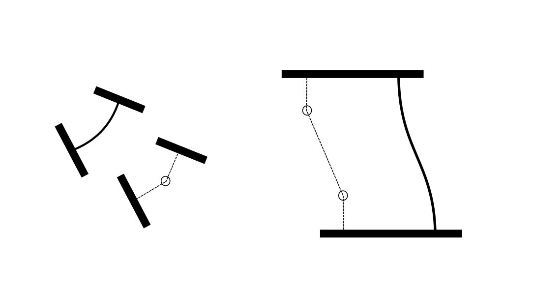
Precisely simulating flexures requires you to deal with geometric nonlinearity and maybe material nonlinearity, which can get very complex mathematically. Fortunately, you can make a pretty good approximation of a flexure with linear springs and links, called the Pseudo-Rigid-Body Model (PRBM). They are explained in Chapter 5 of Compliant Mechanisms. The most obvious PRBM is to model a small flexure as a single torsional spring in the middle. The concept can also be applied to parallel mechanisms, you can see examples of both below.
Using FreeCAD to Design Linkages
I tried several different rigid body solvers, but found them clumsy to use. You would have to define your model using code, or import it from some CAD package. I wanted something I could work on in realtime. I started using FreeCAD to sketch out ideas, using the contraint solver in the Sketcher workbench as a poor man’s rigid body solver. I found that FreeCAD worked fine for my use case (I wasn’t worryed about kinematics or dynamics at this point, I was looking for a mapping between crank angles and end effector position). FreeCAD has a python interface, so I wrote a script that would periodically change the angle of the input link.
I could then change the lengths of links as I watched the linkage cycle, observing how the charactaristics of the path of the foot changed. Once I had something that more or less worked I wrote a second script that recorded the path of the foot as a set of coordinates, then changed the geometry of the foot, and repeated. When it had finished running I had a set of a hundred different paths, and I just had to select the best one. Now that I had my finished PRBM, I set about turning it into the compliant linkage it was supposed to be representing. I replaced all the joints with flexures and filled the spaces between with rigid bodies.

I attempted to run a FEM analyis using CalculiX in Freecad, applying different displacements to try and replicate the effect of the crank turning. The results aren’t good, I suspect because the internal solver is linear. Notice how the pivot hole expands and contracts oddly.
The Printed Linkage
I mirrored the linkage to make a part with two feet with one input and sent it off to a 3D printing service. I did have to reassure them that I wanted the flexures to be that thin, and that I would take the of risk them getting damaged in the post.
As you can see the parallel flexures buckle due to the torque on the foot from the link to the pivot. This is a limitation of using a PRBM, if I had found a better way of modelling the mechanism I might have been able to mitigate it. That being said it still works reasonably well. I ran into my coursework deadline before I ever made a full Strandbeest using my mechanism.